CONTROLLER 9000, DISPENSE VALVE
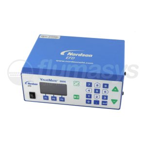
CONTROLLER 9000, DISPENSE VALVE
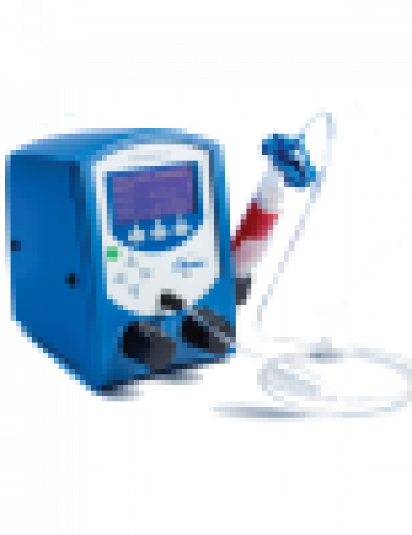
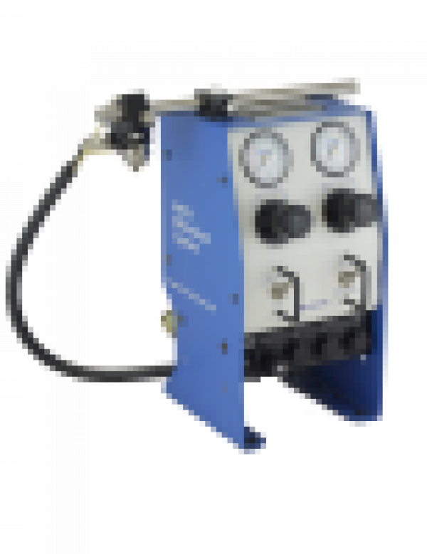
For dual dispense valve control applications, choose EFDʼs advanced technology ValveMate 9000 Controller
Increased Functionality for Increased Results
The ValveMate 9000 controller supports two valve systems, one channel for each valve. Each channel is capable of driving a remote high-speed solenoid valve up to 500Hz. To further achieve greater precision and consistency, the controller incorporates a heating system and an electronic fluid reservoir pressure regulator for each channel.
The ValveMate 9000 can be programmed to automatically change the dispensing parameters over time. This allows the system to compensate for periodically changing conditions, such as viscosity changes as well as dispensing patterns of different sized deposits.
Benefits
• Precise full-to-empty reservoir pressure control
• Setup parameters can be adjusted remotely by PLC
• Auto Increment mode that adjusts dispensing parameters after a certain number of shots or a specific elapsed time
• Accurate control of external system components such as low powered solenoids
• Auto Sequence mode that allows deposit patterns to be repeated automatically
Features
• Programmable dispensing time setting with digital time readout
• Input/output (I/O) communication with host machine PLCs
• Programmable fluid pressure settings
• Dual 24 W temperature controllers for J-type thermocouples
• Dual EPRs (electronic pressure regulators)
• Auto-sequence mode
• 100 individual memory storage cells
• Remote programming capability via external PC or PLC
• A front panel manual dispense cycle key
• Four independent general-purpose input/output (I/O) drivers
• Two end-of-cycle feedback circuits
• Dual variable-voltage (5–24 VDC, 24 W) valve drivers with spike-and-hold capability
• Cycle counter display for each valve driver
• Panel-mountable cabinet
• Alarm indicators
Specifications
Cabinet Size: 255 mm (10.04 in) W x 111 mm (4.36in) H( includes feet) x 214 mm
(8.43 in.) D (to end of fittings)
Weight: 3.45 kg (7.60lb)
Electrical Power Input: 100-240 VAC ± 10%, 2.4 A, 50-60Hz
Feedback Circuits: End of Cycle (EOC) 1-2 and Alarm Out (AO)
Electronic Switch, 24VDC, 100mA maximum
Initiate Circuits: VI 1-2: 5-24 Voltage Initiate Signal (DC)
5-24 Voltage Initiate signal duration: no less than 200µs momentary
or maintained for steady mode operation
Foot Switch (optional): dry contact initiate circuit, 19 mA closure current
• foot switch initiate signal is de-bounced for a period of 20ms
• de-bounce on foot switch signal can be disabled via serial command or by pressing the '5' key during power up.
Time Range: 0.0001–9.9999 sec, 100 μs resolution
Cycle Rate: Up to 500Hz
Product Classification: Installation Category II
Pollution Degree 2
Meets or exceeds CE and CSA requirements

